
Table of Contents
The Project Designer is a new feature in VIOSO 6.
Designer Overview
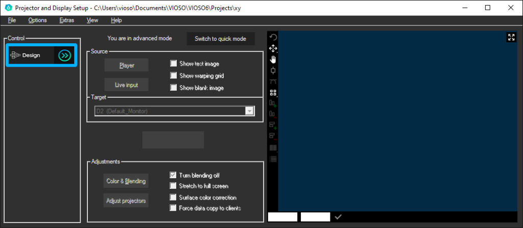
If you want to use the Designer to enter your setup you need to use the Projectmode. At the first start you can only enter the Desingn Tab:
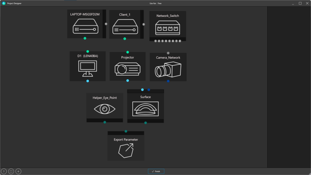
It is the first Step in the Tasklist to create a calibration in the project mode. Here you enter the whole Setup that you are using, the surface you are projecting on and which Fileformat you want to get out of the process:
The project designer recognizes the hardware – basic configuration of the PC on which VIOSO 6 is running. The PC is displayed and the connected devices on the graphics card are inserted. A connected camera is also displayed. The Designer is used to do the whole Setup, from configuration to export.
Nodes
Each node represents an instance of the calibration. Be it a server that outputs the signal or a surface that is projected onto. Up to and including the export settings, most of the advances can be found in the new Designer tab.
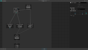
By clicking on the individual nodes, the respective settings can be made in the inspector on the right edge of the screen.
Nodes can be inserted arbitrarily to represent the entire setup that you want to use.
If you have selected a program where you want to use the calibration, only depending nodes are shown and can be inserted.
The black areas are an area where ports can be added or removed with the right mouse button:
Computer
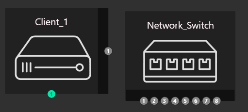
All master/clients that are in the network and should play a role in the measurement must be visible. Connected clients are automatically detected. Active devices can be recognized by the blue “6” logo next to the device. Cameras must be connected only to the master only. A network switch only is required for handling multiple network cameras.
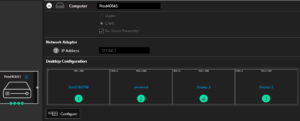
By clicking on Configure you get to the display setup shown above. Here you can see which outputs are assigned to physical devices and these can also be identified by clicking on “IDENTIFY”.
If you work with a mosaic group or display extenders (e.g. Datapath FX4), the displays can also be virtually “split” at this point.
The graphics card outputs are displayed at the bottom of the computer icon. If you move the mouse pointer over a node, the corresponding connection options are offered. It is also possible to connect the nodes via drag and drop.
The graphics card outputs are connected to monitors or projectors
Monitor
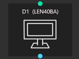
In Case that you are using a Controlmonitor you can insert one and connect it to the right output on your Graphiccard
Projector
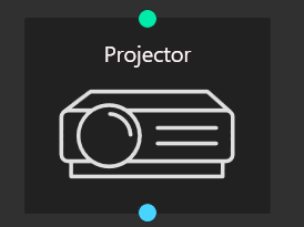
Projectors can be inserted and the properties can be entered, although these initially have no effect on the calibration
Camera
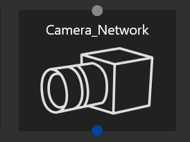
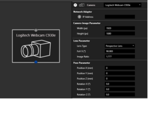
If you click on a camera in the designer, various settings can / must be made.
If the position of the camera is known, the corresponding values can already be entered here. The FOV can be set here and the type of optics
Switch
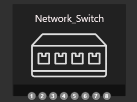
A network switch enables the connection of devices such as servers and cameras.A SWITCH should also be created if a computer has multiple network cards, because it allows the selection of the active adapter.
Projection surface
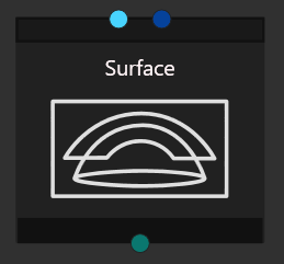
The selection of the surface determines the calibration process. You can choose between the 2D process, in which the calibration must be manually adjusted to the screen, and the 3D process, which adds a 3D object to the calibration. With the help of the 3D object, distortions of the screen are compensated in advance and then only need to be minimally corrected.
The selection of the surface determines the calibration process. You can choose between the 2D process, in which the calibration must be manually adjusted to the screen, and the 3D process, which adds a 3D object to the calibration. With the help of the 3D object, distortions of the screen are compensated in advance and then only need to be minimally corrected.
Objects that do not have a special surface structure are often used as screens.
For these cases a 3D object generator is available, with which the typical surfaces can be created.
The following models are available:
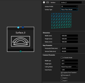
Flat surface
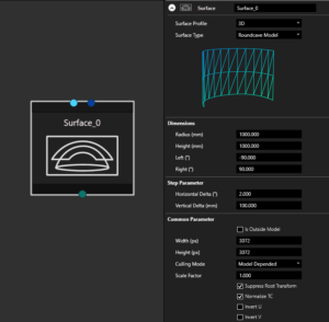
Roundcave / Cylinder / Curvescreen
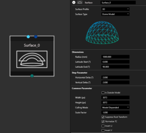
Dome
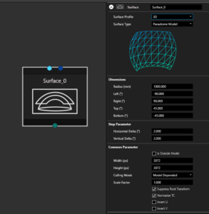
Panadome
if a specific model is needed, it can be selected via “arbitrary model” and then imported
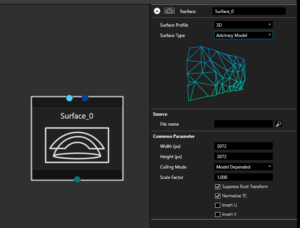
By entering the actual values, an object including a suitable test image is created.
Export

When exporting, parameters such as file format, file name, location and specific values can be set, depending on the export format
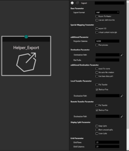
If you have selected an application at startup, the values are already preconfigured appropriately. The individual parameters can be found in more detail in the helpdesk.
Special export nodes are only created if the appropriate selection is made at the start of the project. These nodes cannot be inserted manually.
Eyepoint
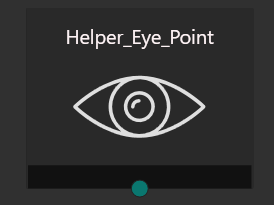
In VIOSO SIM, you can export views from a 3D calibration result. Each view represents a frustum calculated for the corresponding projector (Field of view, position and orientation). By default, the reference for this calculation is an eyepoint located in the origin of the 3D model representing the (0,0,0) point. If you would like to offset this position (e.g. for a driver’s pose, co-pilot seat, high platform..etc) you can use the eyepoint node to set the offset values and connect it to the export node.
Note: This eyepoint node is only used for simulators with a static eyepoint integration (e.g. Prepar3D, DISI). For dynamic eyepoint plugins (e.g. Unreal, Unity, rFpro) the eyepoint position can be defined at runtime or in the VIOSOWarpBlend.ini of the host application
Edge of the screen Tools
|
|
Opens the Help window |
|
|
Opens a selection for display |
|
|
Opens the Insert Devices window. |


Right-click toolbar
Various tools are available in the designer:
Right mouse button opens the quick menu for inserting devices / export and customizing the display
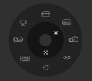
to insert a node you only have to click on one of the icons. After insertion, the nodes are configured by selecting them.
Connection of Nodes
The nodes must be connected to each other. The connections must correspond to the actual conditions.
The servers as well as the camera are connected to each other with a switch in between.
Network Connections between:
Computer Switch Camera
Video connections between:
Computer Monitor Projector
View Connections between:
Projector Surface Camera Eyepoint
Multiclientsetup
It is possible to create multiclient setups in the designer. For this purpose, all servers involved should first be prepared. This means that the same version of Vioso is installed. The network must be set up. The graphics cards must output the correct signal and the projectors must be connected.
VIOSO 6 must run in client mode on the servers. The camera signal must be present at least at the master.
When everything is prepared, you can start adding the first client in the designer. If everything is configured correctly, all clients now exist with their IP in a dropdown menu where the corresponding devices can be selected. The software recognizes the graphics card settings and creates the client accordingly in the designer.
As soon as all necessary clients have been inserted, the corresponding projectors must be added. Then all ports are connected according to the use. The clients with network and projectors, as well as the projectors with the surface.
Design is ready
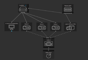
This is how a complete Setup can look like

a standalone setup with one computer and three projectors
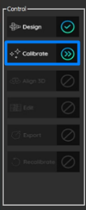
When you are ready, click “Finish”, and you will be redirected to the main window.
The Design Tab will have a blue tick on its right, and you will be able to continue to the next step, which is the “Calibrate” button.
If a connection is missed in the Design phase, the “Design” Button will appear as an exclamation mark. And you need to go back to the Design and check if something was missed.